Product Overview
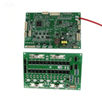
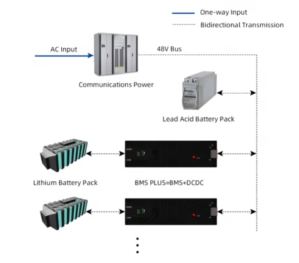
The TB03-P16S series is a high-performance, modular BMS designed for low-voltage lithium battery energy storage systems (home storage, telecom backup, industrial racks). Supporting up to 16 cells in series, it integrates 16 voltage detection channels, 5 temperature sensors (4x cell + 1x MOSFET), and delivers comprehensive protection against overcharge, over-discharge, overcurrent, short circuit, overtemperature, and undertemperature. Advanced safety architecture with MOSFET + controllable fuse + breaker trip provides three-level redundancy, eliminating single-point failure risks.
✅ Key differentiators: Automatic address assignment for parallel operation, precharge circuit, passive balancing (100mA), LCD & LED dashboard options, remote monitoring via WiFi/Bluetooth, and compatibility with major inverter protocols (Deye, Growatt, Solis, Victron, SMA, etc.).
⚡ Core Features
- 16-cell voltage detection (2~4.5V, ±10mV accuracy)
- Total pack voltage monitoring (0~60V, ±0.1%)
- High-precision current sense: >50A ±2% / ≤50A ±1A
- 5x temperature inputs (NTC) – accuracy ≤ ±3°C
- Passive balancing: 100mA ±20% (charge & idle)
- Triple protection pathway: MOSFET cutoff + controlled fuse + breaker trip coil
- Precharge circuit (2s precharge time) eliminates inrush current
- SOC accuracy ≤ ±5% with auto-calibration (full charge/discharge detection)
- History data logger (≥10,000 event records)
- One-key power-on & SOP (state of power) estimation
📡 Communication & Parallel
- 2x isolated RS485 (inverter & parallel bus)
- 1x CAN bus (supports Pylontech, Victron, Growatt, etc.)
- 1x RS232 for PC / HMI debugging
- Optional WiFi / Bluetooth module for remote cloud monitoring
- Auto-addressing parallel: up to 16 BMS units in daisy-chain via RS485-2
- Master-slave architecture with single host configuration for parallel pack management
- Real-time sync of SOC, alarms, and protection status
- Upper computer (PC software) for parameter tuning, firmware upgrade, diagnostics
Technical Specifications
| Model options |
TB03-P16S100A / 120A / 150A / 200A / 300A |
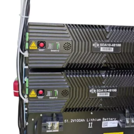
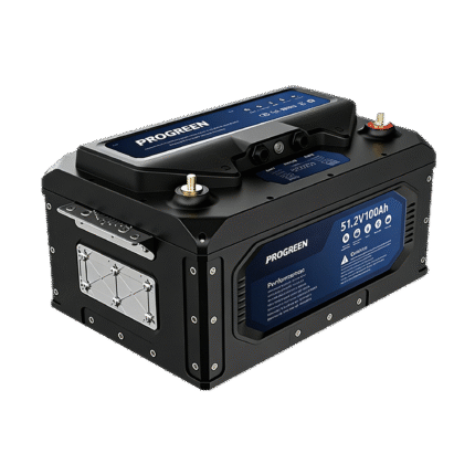
| Nominal voltage (16S LiFePO₄) |
51.2 VDC |
| Max continuous charge / discharge current |
100A / 120A / 150A / 200A / 300A (model dependent) |
| Voltage detection range (single cell) |
2.0 ~ 4.5V DC, accuracy ≤ ±10mV @ -10~55°C |
| Total voltage range & accuracy |
0~60V, ≤ ±0.1% |
| Current measurement accuracy |
>50A: ±2% ; ≤50A: error ≤1A |
| Temperature channels / accuracy |
5 channels (4 cell + 1 MOS) · ≤ ±3°C @ -40~85°C |
| Passive balancing current |
100mA ±20% |
| Precharge circuit |
Built-in, 2000ms precharge time |
| Operating temperature range |
-20°C ~ +70°C |
| Storage temperature |
-40°C ~ +85°C |
| Protection degree |
IP20 (natural convection cooling) |
| Mainboard dimensions (L×W) |
150 × 100 mm |
| Power board size (depends on current) |
115×110mm (100/120A) / 170×110mm (150/200A) / 300×120mm (300A) |
| LCD display (optional) |
106 × 71 mm (with menu keys) |
| Sleep mode power management |
Deep sleep after 1440min idle, wake-up via communication or charge current |
Intelligent Protection & Recovery
🔋 Voltage & Current Protection
- Cell overvoltage protection: ≥3650mV (release @ <3380mV or discharge >3A)
- Cell undervoltage protection: ≤2700mV (release @ >2950mV or charge >1A)
- Total overvoltage: ≥58.4V, release @ <54.0V
- Charge / discharge overcurrent protection (2 levels with timing & lock after 3 attempts)
- Short-circuit protection: <220µs response, auto-recover after 1min (max 3 attempts)
🌡️ Temperature & System Protection
- Charge high temp protection: ≥60°C (release <55°C)
- Charge low temp protection: ≤0°C (release >5°C)
- Discharge high temp: ≥65°C, release <60°C
- Discharge low temp: ≤-20°C, release >-15°C
- MOSFET overtemperature protection: ≥105°C (release <85°C)
- Differential temperature protection (cell imbalance >15°C triggers shutdown)
- Emergency failure / fuse blown → lockout with alarm LED
🔁 Automatic recovery & fail-safe design – Most protections auto-recover when conditions normalize; persistent overcurrent/short events lock after repeated faults, requiring manual restart for absolute safety.
Inverter Compatibility & Industry Protocols
Pre-integrated communication stacks for seamless integration with leading hybrid and off-grid inverters. Protocol selection via LCD display or PC tool.
RS485 protocol support:
DeyeVoltronicGrowatt
PylontechSRNEINVT
TG-EPSolis
CAN protocol support:
DeyeSofarGrowatt
VictronLXP (Pylontech)SMA
SRNESol-ark
Quick setup via LCD display or PC master software – change protocol on-the-fly, configure battery capacity, OVP/UVP thresholds, current limits, and monitor real-time data logs.
Scalable Parallel Operation (Max 16 units)
📈 Automatic addressing & parallel setup
- Connect RS485-2 ports between BMS units (daisy-chain)
- Power on sequentially; default auto-addressing mode assigns unique IDs
- Set total parallel number via host BMS (LCD or PC software); no need to configure slaves
- Host automatically manages current sharing, SOC synchronization, and global protection
- Recommended voltage difference between packs ≤3V before parallel power bus connection
- Internal communication alarm alerts if any slave is offline
⚙️ Wiring & startup recommendation
- Ensure communication wiring done FIRST, then connect power bus
- Startup order: Slave BMS units → Host BMS → Inverter
- Host BMS saves parallel number permanently even after power cycle
- Support mixed current capacity? Host negotiates max allowed charge/discharge current based on lowest rated pack
Visual & Control Interface
🖥️ LCD Display (optional)
- 2.8” graphic LCD with numeric SOC, voltage, current, temperature, alarms
- Navigation keys: MENU/UP/DOWN/ENTER → view parameters, clear faults, set protocols, parallel quantity
- Real-time status & historical alarm browsing
💡 LED indicator board & onboard LEDs
- 4 SOC LEDs (0-25%, 25-50%, 50-75%, 75-100%)
- ALM LED: flashes for warning, solid for protection event
- Charge/discharge direction indication via LED pattern
- Sleep mode: all LEDs off
Smart SOC & SOH Management
Coulomb counting + voltage-based calibration: SOC accuracy ≤ ±5% under normal operation. Automatic full-charge calibration when pack voltage >56.0V and charge current <1.5A, or highest cell voltage ≥3650mV. Low-voltage calibration resets SOC to 0% when any cell ≤2700mV or total voltage ≤43.2V. SOH estimation based on cycle counting (default 200 cycles per 1% degradation) — prolong battery life and improve reliability.
🔄 Balancing strategy: passive balancing enabled in charge and standby modes when max cell voltage >3400mV and delta >30mV, effectively maintaining voltage consistency and optimizing usable capacity.
Ordering Information & System Integration
| Base model |
TB03-P16S (mainboard + power board combo) |
| Current rating option |
100A / 120A / 150A / 200A / 300A |
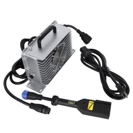
| Accessories included |
Voltage sampling harness, NTC sensors (5 pcs), power board interconnect cable, switch cable, optional external trip coil wire, LCD display (optional), WiFi/Bluetooth module (optional) |
| Firmware / software |
PC master software V0.15.2+ ; LCD firmware V3.4 ; protocol configurable |
| Approvals & standards |
RoHS, designed according to GB/T 7251.1 altitude derating >2000m, natural convection cooling |