Blog
Boost Converter Basics: How Step-Up Voltage Regulators Work and When to Use Them
Boost Converter Basics: How Step-Up Voltage Regulators Work and When to Use Them
Boost Converter Basics: How Step-Up Voltage Regulators Work and When to Use Them
📅 Updated: April 2026 | ⏱ 9 min read | 🔋 DC-DC Conversion
In the world of power electronics, sometimes you need a higher voltage than your source can provide. That’s where the boost converter—also known as a step-up converter—comes into play. This essential switching regulator takes a lower DC input voltage and produces a higher DC output voltage with impressive efficiency. From battery-powered devices to automotive systems, boost converters are everywhere. In this guide, we’ll explain the basic operating principles of a boost converter, derive the key duty cycle equation, discuss efficiency and component selection, and explore the most common applications where a step-up voltage regulator is the right choice.
What Is a Boost Converter?
A boost converter (or step-up converter) is a type of DC-DC switching converter that outputs a voltage higher than its input voltage. Unlike a linear regulator that dissipates excess voltage as heat, a boost converter stores energy in an inductor during the switch-on period and releases it at a higher voltage during the switch-off period. This energy storage and transfer mechanism allows the output voltage to be regulated above the input voltage, making it indispensable for applications where the available supply voltage is lower than what the load requires.
Typical applications include:
- Powering 5V USB outputs from a single 3.7V Li-ion battery
- Boosting 12V from a 9V battery or a 5V USB power bank
- Generating 24V or 48V for LED lighting from a 12V system
- Photovoltaic (solar) systems where panel voltage is lower than battery charging voltage
- Electric vehicles and portable medical devices
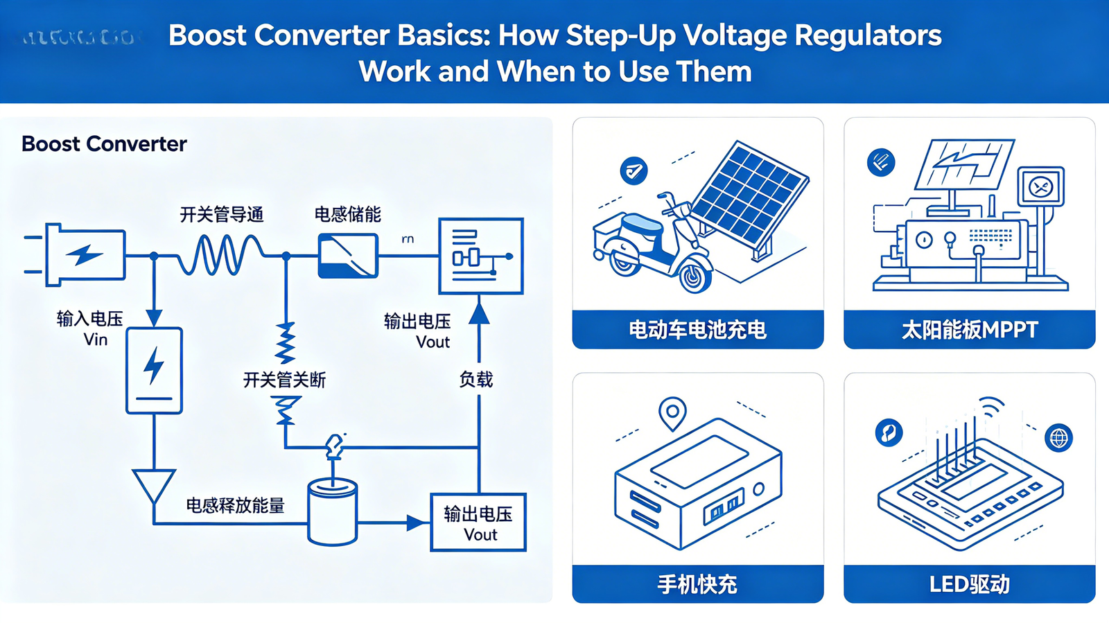
How a Boost Converter Works: Basic Operating Principle
The heart of a boost converter circuit consists of an inductor, a switching transistor (typically a MOSFET), a diode, and an output capacitor. The operation alternates between two states controlled by the switch:
State 1: Switch ON (Energy Storage Phase)
When the MOSFET switch closes, current flows from the input source through the inductor and the switch to ground. The inductor stores energy in its magnetic field, and the current through it increases linearly. During this phase, the diode is reverse-biased (since its anode is at ground potential), so the output capacitor supplies current to the load. No energy is transferred from input to output during this period.
State 2: Switch OFF (Energy Transfer Phase)
When the MOSFET opens, the current through the inductor cannot change instantaneously. The inductor reverses its voltage polarity to keep current flowing, forward-biasing the diode. The stored energy is now released through the diode into the output capacitor and the load. Because the inductor’s voltage adds to the input voltage (VL + Vin), the output voltage is higher than the input. The output capacitor smooths the pulsed current, providing a steady DC voltage.
By varying the duty cycle (the ratio of ON time to switching period), the controller adjusts how much energy is stored and transferred, thereby regulating the output voltage.
💡 Key Insight: In a boost converter, the input current is continuous (always flowing), while the output current is discontinuous (pulsating). This means the output capacitor must be large enough to supply load current during the switch-on phase and to filter the ripple.
Boost Converter Duty Cycle and Output Voltage Formula
The relationship between input voltage (Vin), output voltage (Vout), and duty cycle (D) for an ideal boost regulator operating in Continuous Conduction Mode (CCM) is given by:
Vout = Vin / (1 – D)
Where D is the duty cycle (0 < D < 1). Rearranging, the duty cycle is:
D = 1 – (Vin / Vout)
For example, to boost 5V to 12V, the required duty cycle is D = 1 – (5/12) ≈ 0.583 (58.3%). Note that as Vin decreases, D must increase to maintain the same Vout. The theoretical maximum output voltage is limited by parasitic elements and practical duty cycle limits (typically 80–90% for most ICs).
For real converters, the duty cycle also depends on the forward voltage drop of the diode (VF) and the voltage drop across the switch (VSW). The more accurate formula is:
Vout = (Vin – VSW) / (1 – D) – VF
Boost Converter Efficiency and Key Component Selection
The efficiency of a dc dc boost converter typically ranges from 80% to 94%, depending on operating conditions and component quality. Losses arise from:
- Inductor core and copper losses (I²R): Use an inductor with low DC resistance (DCR) and a core material suited for the switching frequency.
- MOSFET conduction and switching losses: Choose a MOSFET with low RDS(on) and low gate charge.
- Diode forward voltage drop: A Schottky diode (VF ≈ 0.3–0.5V) is much better than a standard silicon diode (0.7–1.0V). For higher efficiency, use synchronous rectification (a second MOSFET instead of a diode).
- Capacitor ESR: Low-ESR ceramic or polymer capacitors reduce ripple and losses.
To maximize boost converter efficiency, operate the converter at a moderate switching frequency (e.g., 100–500 kHz) to balance inductor size and switching losses, and ensure the inductor does not saturate at peak current. The inductor peak current in a boost converter is approximately IL,pk = Iin,avg + ΔIL/2, and it can be significantly higher than the output current. For a 5V to 12V boost with 1A output, the average input current is about 2.7A (assuming 90% efficiency).
⚠️ Critical Consideration: Boost converters have a right-half-plane zero (RHPZ) in the control-to-output transfer function when operating in CCM. This makes compensation more challenging; the crossover frequency must be set below the RHPZ frequency (typically less than 1/3 to 1/5 of the RHPZ) to ensure stability. For low-power DCM operation, the RHPZ disappears, simplifying control.
Continuous vs. Discontinuous Conduction Mode (CCM vs. DCM)
A boost converter can operate in two distinct modes:
- Continuous Conduction Mode (CCM): The inductor current never falls to zero during the switching cycle. CCM is typical for medium to high power (above a few watts) and offers lower peak currents but introduces the RHPZ, complicating loop compensation.
- Discontinuous Conduction Mode (DCM): The inductor current falls to zero before the next cycle begins. DCM occurs at light loads or when using a smaller inductor. It has no RHPZ, simplifying control, but peak currents are higher, and efficiency may drop at heavy loads.
Many boost regulator ICs are designed to transition between CCM and DCM automatically to maintain efficiency across the load range. For designs with widely varying load currents, this feature is very beneficial.
When to Use a Boost Converter (And When Not To)
A step-up converter is the right choice when you need a higher voltage than your available source, but there are limits and alternatives:
- Use a boost converter when:
- You need to generate 5V, 9V, or 12V from a single-cell Li-ion battery (3.0–4.2V).
- You want to power 12V LED strips or fans from a 5V USB power bank.
- You are designing a portable device that must operate from a low-voltage battery but requires higher voltages for peripherals.
- You need to boost a solar panel voltage to charge a higher-voltage battery.
- Avoid a boost converter when:
- You need very high step-up ratios (e.g., 3V to 300V). A flyback converter (isolated) is more suitable.
- Your output voltage is lower than the input – use a buck converter instead.
- You require extremely low output ripple and noise; a linear regulator might be better post-boost.
For applications where the input voltage can be both above and below the desired output (e.g., a 12V battery that can dip to 10V and rise to 14V), a buck-boost converter or SEPIC is the appropriate topology.
🔧 Pro Tip: When designing a boost converter, always calculate the peak inductor current and ensure the inductor’s saturation current rating exceeds that peak by at least 20%. Use a low-ESR ceramic capacitor at the input to reduce input voltage ripple, which can be significant due to the pulsed input current of a boost converter (the input current is continuous but still contains switching ripple).
Practical Example: 5V to 12V Boost Converter for USB-PD
Imagine you need to power a 12V, 1A (12W) fan from a 5V USB power bank. With a target efficiency of 90%, the input power is about 13.33W, so input current ≈ 2.67A. Using a boost converter IC like the MT3608 (common for low-power applications), set the feedback resistors to obtain 12V. Choose an inductor of 10–22 µH rated for at least 3.5A saturation. The output capacitor should be a 100 µF low-ESR electrolytic in parallel with a 10 µF ceramic to handle ripple. With proper layout, such a converter can run efficiently and reliably.
Frequently Asked Questions
Can a boost converter be used as a buck converter?
No, a boost converter only steps up voltage. To step down, you need a buck converter. However, a buck-boost converter can do both.
Why does my boost converter get hot even with moderate load?
Check the inductor saturation; if the inductor saturates, current spikes cause excessive losses and heating. Also, ensure the diode is a Schottky type and that the MOSFET has sufficiently low RDS(on). Insufficient copper area for heat dissipation can also be a problem.
What is the maximum voltage a boost converter can produce?
The theoretical maximum is very high, but practical limits are set by component voltage ratings and the duty cycle limit (usually 85–90%). For very high step-up ratios (1:10 or more), a flyback converter with a transformer is more practical.
How does a boost converter affect battery life?
Because a boost converter draws more current from the battery than it delivers to the load (power conservation: Pin = Pout/η), it can deplete batteries faster than a direct connection would. However, its high efficiency (often 90%) minimizes this penalty compared to linear solutions.
Conclusion: Master the Boost Converter for Your Next Design
The boost converter is a fundamental building block in power electronics. Understanding its operating principles, duty cycle relationship, and efficiency considerations enables you to design reliable, high-performance step-up power supplies. Whether you are boosting a battery voltage to drive LEDs, creating a USB power bank output, or implementing a photovoltaic MPPT charger, the step-up voltage regulator is an indispensable tool. By selecting quality components, paying attention to layout, and respecting the limits of continuous conduction mode, you can achieve excellent results. Start with a proven IC, calculate your inductor and capacitor values, and test your design under expected load conditions. With practice, you’ll master the art of boosting voltage efficiently and reliably. © 2026 Power Electronics Guide – Your resource for boost converter design, dc dc boost converter tutorials, and step-up power supply basics.